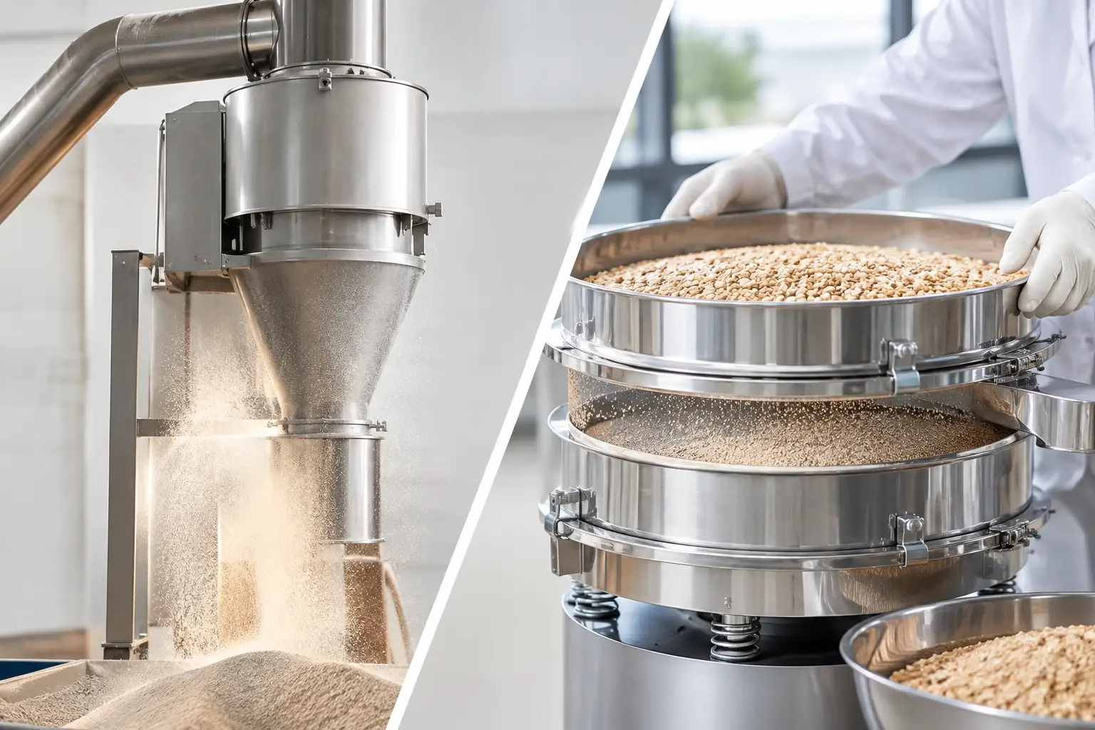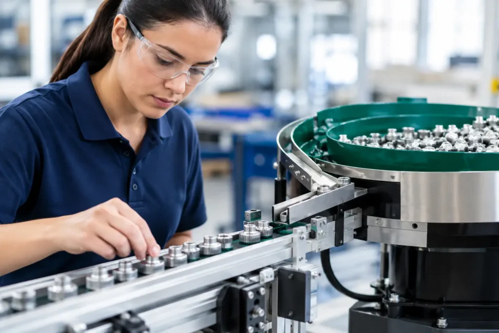
A feeder that misses its target by a small amount on every cycle can become a significant production problem by the end of a shift. In a batch process, the result may be off-spec product, rework, or a failed quality review. In a continuous process, it can mean unstable downstream operation, inconsistent blend quality, excess ingredient consumption, and lost throughput. Understanding how to improve feeder accuracy starts with a practical fact: the feeder is only as accurate as the material behavior, mechanical design, control strategy, and upstream conditions allow it to be.
For powders, granules, flakes, pastes, and other bulk solids, there is no universal adjustment that corrects every feeding problem. A free-flowing granular material may respond well to a basic volumetric feeder. A cohesive, aerated, or moisture-sensitive powder may require agitation, hopper conditioning, gravimetric control, and a different discharge geometry. The right solution is application-specific, because the material sets the operating limits.
Start With the Accuracy Requirement
Before changing equipment or tuning controls, define what accuracy means for the process. A feeder may be expected to deliver a precise short-term dose, maintain a stable average rate over several minutes, or hit a cumulative total over an entire batch. These are related measures, but they are not interchangeable.
For example, a feeder supplying a minor ingredient to a high-value batch may need tight dose-to-dose repeatability. A continuous feeder supplying a bulk ingredient to an extruder may tolerate small instantaneous variation if its long-term mass flow remains controlled. Establish the required tolerance, the time period over which it applies, the operating rate range, and the consequences of deviation. This gives engineering, operations, and quality teams a common basis for evaluating performance.
It also prevents unnecessary overdesign. Specifying extreme accuracy for a material that naturally fluctuates because of particle segregation, entrained air, or moisture variation can add cost without improving finished-product quality. The goal is controlled performance at the point where it matters to the process.
How to Improve Feeder Accuracy at the Material Interface
Most feeder issues begin before the material reaches the metering device. Bulk solids do not behave like liquids. They can bridge over an outlet, form stable ratholes, flood when aerated, compact under head pressure, segregate by particle size, or smear and build up on contact surfaces. Each behavior changes the amount of material available to the feeder.
A consistent material presentation to the feeder is essential. The hopper outlet, transition angles, internal surfaces, agitation method, and refill arrangement should be selected for the actual material, not for an assumed “typical powder.” If the product is cohesive, a properly designed agitation system or live-bottom arrangement may be necessary to maintain mass flow. If the powder is easily aerated, hopper venting and refill velocity must be controlled to prevent density changes that affect volumetric delivery.
Particle size and bulk density deserve particular attention. A blend containing particles with different sizes or densities can segregate during conveying, storage, or hopper refill. The feeder may then be mechanically repeatable while delivering a changing composition. In those cases, improving feeder accuracy requires attention to transfer methods, hopper geometry, and refill sequence, not simply a change to feeder speed.
Material characterization should include loose and packed bulk density, flowability, moisture sensitivity, particle-size distribution, compressibility, and tendency to segregate or adhere. Testing under realistic operating conditions is more useful than relying on a material data sheet. Product behavior often changes after milling, blending, drying, conveying, or exposure to plant humidity.
Select the Right Feeding Principle
Volumetric feeders meter material by displacement. Their performance depends on the feeder mechanism delivering a consistent volume per revolution or stroke and on the material maintaining a stable bulk density. They can be effective for free-flowing materials and applications where moderate accuracy is acceptable, but density shifts can directly affect mass flow.
Gravimetric feeders measure mass and correct the feed rate using load-cell feedback. Loss-in-weight feeders are commonly used when continuous, high-accuracy dosing is required. As material leaves the weigh hopper, the controls calculate the mass-loss rate and adjust the feeder drive to maintain the setpoint. This compensates for many variations that would affect a volumetric feeder.
Gravimetric control does not eliminate mechanical or material problems. A loss-in-weight feeder cannot correct a bridge that interrupts flow, a poorly sized screw that pulses at low rates, or a refill event that introduces major disturbance. It provides measurement and correction, but the feeder and hopper must still supply a stable, controllable stream of material.
The feeder mechanism must also suit the product. Single-screw feeders often perform well with free-flowing powders and granules. Twin-screw designs can provide more positive, uniform handling for cohesive materials, low-rate applications, or products prone to inconsistent screw filling. Vibratory feeders may be appropriate for certain granules or fragile materials, while belt feeders are often selected for larger particles, difficult bulk solids, or higher capacities. The correct choice depends on rate, material behavior, sanitation requirements, wear, and acceptable particle degradation.
Control Refill Events and Head Pressure
Refill is one of the most common sources of feeder variation. During refill, the scale reading is affected by incoming material, and the amount of material above the metering device changes. That change in head pressure can alter screw fill, compaction, and discharge rate.
A well-designed loss-in-weight system shifts temporarily to volumetric operation during refill, then returns to gravimetric control after the hopper has settled. The transition must be tuned for the material and process. Refill too frequently, and the feeder spends excessive time outside normal gravimetric control. Refill too aggressively, and the hopper may aerate, overload, or disturb material flow. Refill too slowly, and the feeder can run empty or approach an unstable low-level condition.
The target is a repeatable refill cycle with enough usable weigh range between high and low levels. Upstream conveying capacity, refill valve response, dust collection, hopper venting, and control logic all affect this cycle. Treating refill as a separate engineered operating state produces better results than viewing it as a simple hopper top-up.
Calibrate the Entire Measurement Chain
Feeder accuracy depends on trustworthy measurement. For gravimetric systems, that means more than periodically checking the load cells. The complete weighing system includes load cells, mounting hardware, flexible connections, cabling, signal conditioning, mechanical stops, and the controls platform.
A weigh hopper should be mechanically isolated from surrounding structure. Rigid inlet pipes, outlet connections, dust-collection ducting, cable trays, or guarding can introduce forces that distort the weight signal. Flexible connections must be installed without creating tension or contact points. Mechanical interference is especially likely after maintenance work or production-line modifications.
Calibration should verify zero, span, linearity, and repeatability across the normal operating range. Test weights are useful, but process validation should also compare feeder totals against an independent, traceable reference over representative run durations. A system can pass a static calibration check and still underperform during production because of vibration, refill disturbances, or unstable material flow.
For volumetric feeders, establish a material-specific calibration curve rather than relying on a single speed-to-rate assumption. Verify output at multiple operating speeds, because screw fill and material slip may change across the turndown range. Recheck calibration when the supplier, lot, particle size, moisture level, or upstream process changes.
Tune Controls for Stability, Not Constant Correction
A poorly tuned control loop can make a mechanically capable feeder look inaccurate. If the controller responds too aggressively to normal signal noise, it may overcorrect and create rate oscillation. If it responds too slowly, actual drift can persist long enough to affect the process.
Control settings should reflect the feeder’s response time, the material’s behavior, scale resolution, and the downstream process sensitivity. Filtering can reduce noise, but excessive filtering delays detection of a real upset. Similarly, faster control action is not always better when the feeder has a slow material residence time between the metering element and the discharge point.
Use trend data to distinguish random variation from repeatable patterns. A rate disturbance occurring at every refill points toward refill control, head pressure, or aeration. A gradual drift may indicate changing bulk density, wear, buildup, or material conditioning. Cyclic pulsation can point to screw geometry, drive performance, or inconsistent screw filling. Data should direct the corrective action rather than encouraging repeated manual adjustments.
Maintain the Mechanical Conditions That Accuracy Requires
Wear and buildup change feeder behavior gradually, which makes them easy to overlook. Screw flights, agitators, bearings, seals, drive components, and flexible connections should be inspected based on operating hours, material abrasiveness, and process criticality. Abrasive minerals and powders can alter clearances and reduce metering consistency. Sticky products can reduce effective volume or create intermittent release.
Cleaning procedures matter as much as inspection frequency. Residual material in a screw, hopper, or transition can absorb moisture, harden, contaminate the next batch, or change flow behavior. In regulated applications, cleaning and calibration records should support the site’s validation and quality requirements.
A practical reliability program should monitor feeder rate deviation, refill duration, motor load, hopper level, load-cell signal stability, and maintenance findings. These indicators provide early warning before an accuracy issue becomes a production event.
Treat the Feeder as Part of a System
The best feeder cannot compensate for a poorly integrated process. Upstream milling may create a wider particle-size distribution. Pneumatic conveying may aerate the powder. A poorly positioned dust collector can influence hopper pressure. Downstream equipment may impose pressure fluctuations, vibration, or changing demand. Each condition can appear at the feeder as an accuracy problem.
For complex applications, feeder performance should be evaluated as part of the complete handling, weighing, and processing system. One engineering standard across material transfer, hopper design, metering equipment, controls, and downstream equipment reduces the gaps where variability often develops. Proc-X applies this system-level approach by starting with the material and process objective, then engineering the interfaces that determine sustained performance.
When feeder accuracy matters, do not begin with a speed adjustment. Begin by confirming what the process must achieve, how the material behaves, and which part of the system is creating variation. That discipline turns feeder accuracy from a recurring troubleshooting task into a controlled production capability.