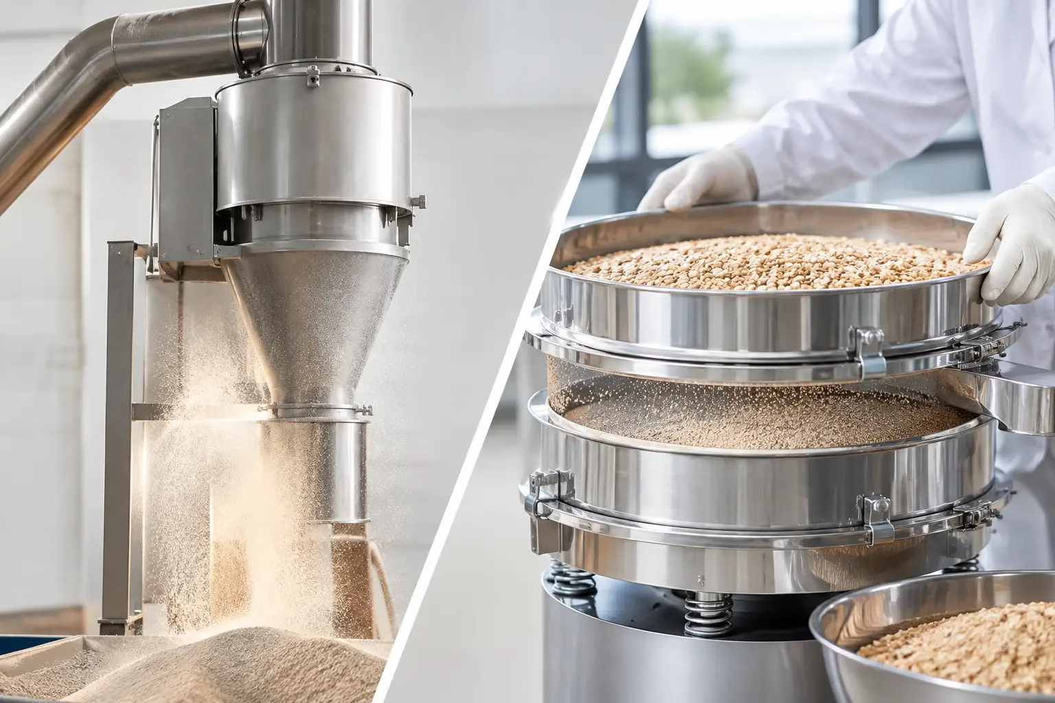
A hopper bridge can turn a well-designed production line into an intermittent batch operation. The feeder may continue to run, controls may show an acceptable level, and downstream equipment may be ready, yet no material reaches the outlet. Knowing how to stop hopper bridging starts with treating it as a material-and-system problem, not simply a hopper problem.
Bridging occurs when a stable arch of powder or granules forms above the hopper outlet. The material supports its own weight, interrupting flow until an operator intervenes or a flow aid breaks the arch. The immediate cost is lost throughput. The larger risk is inconsistent feeding, batch variation, unplanned cleaning, operator exposure, and equipment damage caused by repeated manual intervention.
What causes hopper bridging?
A bridge forms when the forces holding particles together exceed the forces pulling material toward and through the outlet. Cohesive strength may come from moisture, electrostatic charge, fat content, fine particle size, compaction, crystal structure, temperature change, or a broad particle-size distribution. In many applications, several of these factors are present at once.
Hopper geometry then determines whether the material can release. A shallow hopper angle, undersized outlet, abrupt transition, internal ledge, or poorly positioned inlet can create a stagnant region where material consolidates. Even a hopper that performed acceptably with one formulation can bridge after a supplier change, a particle-size adjustment, or a seasonal humidity shift.
Bridging should also be distinguished from rat-holing. With rat-holing, material flows through a narrow channel above the outlet while stagnant material remains against the hopper walls. Both conditions reduce reliable discharge, but they require different design responses. A bridge blocks the outlet. A rathole indicates that the hopper is producing funnel flow rather than moving the full inventory toward discharge.
How to stop hopper bridging: start with the material
The most reliable solution begins with representative material characterization. Product data sheets rarely provide enough information to design a dependable discharge system. Materials should be evaluated in the condition in which they will actually be stored, conveyed, and fed, including expected moisture range, temperature, bulk density, particle-size distribution, and residence time.
Flow-function testing establishes how a material consolidates and the outlet size required to prevent a stable arch at a defined stress condition. Wall-friction testing helps establish hopper wall angle and liner requirements. For difficult products, testing should include the effects of vibration, aeration, shear, and repeated refill cycles. A powder that flows after fresh loading may behave very differently after sitting under head pressure for eight hours.
This work is particularly critical for fine powders, hygroscopic ingredients, spray-dried materials, active pharmaceutical ingredients, mineral blends, battery powders, and formulations containing fats, binders, or irregular particles. It is also essential when a production line must accommodate several products. Designing only for the easiest material creates an avoidable operating constraint.
Design for mass flow where consistency matters
For processes that require stable dosing, batching, or continuous feeding, mass flow is usually the preferred hopper flow pattern. In mass flow, material moves along the walls and toward the outlet as inventory is withdrawn. This reduces stagnant zones, limits segregation, and lowers the probability of bridging and rat-holing.
Achieving mass flow is not a matter of specifying a steep cone in isolation. The hopper angle must be matched to the measured wall friction of the material and the selected construction material or liner. The outlet must be large enough to prevent arching under the anticipated consolidation load. Transitions from the hopper into the feeder must also be smooth, with no ledges, abrupt reductions, or changes in shape that create a restriction.
A round outlet is often appropriate for many powders, but it is not automatically the best choice. Elongated slot outlets can provide a more effective opening for cohesive materials and may better match the inlet geometry of a screw feeder. The correct configuration depends on material behavior, required throughput, and the withdrawal device below the hopper.
Hopper capacity deserves the same level of attention. Excessive material head can increase consolidation and make a cohesive product harder to discharge. Conversely, a hopper that cycles too frequently may introduce air, segregation, or refill disturbances that affect feeder performance. The right storage volume supports production demand without creating unnecessary residence time or compressive load.
Match the hopper to the feeder
A feeder cannot correct a hopper that does not discharge consistently. Screw, twin-screw, belt, vibratory, and loss-in-weight feeders each impose different withdrawal patterns at the outlet. A single screw may pull material preferentially from one area, while a twin-screw feeder may require a broader, more uniform supply zone to maintain fill and accuracy.
The interface should be engineered as one assembly. The outlet shape, agitator clearance, screw orientation, inlet height, and control strategy all affect how material reaches the feeder. If a loss-in-weight feeder is continually compensating for fluctuating bulk density or inconsistent refill, the root cause may be upstream hopper flow rather than feeder calibration.
Use flow aids selectively, not as a substitute for design
Flow aids can be effective when applied to a properly engineered hopper. They are less effective when used to compensate for an undersized outlet or unsuitable wall angle. In those cases, the aid may provide temporary relief while increasing maintenance, product degradation, or process variability.
Common options include vibration, external pneumatic or mechanical agitators, air pads, fluidization, internal live-bottom devices, and hopper activators. Each has a distinct operating range and trade-off.
Vibration can release a bridge, but excessive or continuous vibration may compact some powders, fatigue equipment, generate fines, or cause segregation. Air pads and fluidization can reduce wall friction for suitable dry powders, but they can also alter bulk density, introduce moisture concerns, or disturb a gravimetric feed process. Internal agitators can provide controlled discharge for cohesive products, but their geometry, speed, and sealing must be designed to prevent product damage, buildup, and cleanability issues.
For sanitary, pharmaceutical, or high-value applications, the selection must also account for clean-in-place requirements, containment, material traceability, and validation. A flow aid that solves discharge but complicates cleaning or contaminates the product is not a complete solution.
Control the operating conditions that create bridges
Many bridging events are triggered by conditions outside the hopper. Humid plant air can change a hygroscopic powder within hours. Warm material entering a cooler vessel can condense moisture on internal surfaces. Pneumatic conveying may change particle attrition or introduce air that affects bulk density. Long residence time can allow a material to cake under load.
A practical operating review should examine material receipt, storage, conveying, hopper refill, and discharge as a connected process. Confirm whether bridges occur after downtime, at a particular fill level, during certain weather conditions, or after a formulation change. These patterns often identify the real mechanism more quickly than repeated adjustments to vibration settings.
Controls can also reduce the impact of unavoidable variability. Level measurement should be selected and located to detect true inventory, not merely a cavity created by rat-holing. Feeder torque, motor load, weight-loss rate, refill duration, and high-level alarms can be trended to reveal deteriorating flow before a complete blockage stops the line. For automated systems, interlocks should prevent downstream equipment from running out of material while upstream equipment continues to cycle unnecessarily.
Validate the solution under production conditions
A successful trial is more than a single discharge test. The system should be tested across the material’s expected operating range, including maximum and minimum moisture, full and low hopper levels, extended hold times, normal refill frequency, and required production rates. If the line handles multiple products, each product should be evaluated against the same performance criteria.
Acceptance criteria should focus on measurable outcomes: stable feed rate, repeatable batch weight, no manual bridge breaking, acceptable product integrity, and predictable restart after planned downtime. This approach protects the whole process, from ingredient handling through mixing, packaging, and quality release.
Proc-X approaches hopper discharge as part of the complete material-handling and processing system. That perspective matters because a reliable hopper must work with the feeder, conveying method, controls, sanitation strategy, and production objective under one engineering standard.
The most effective bridge-prevention project does not begin with a vibrator or a larger motor. It begins with the material, confirms the governing flow mechanism, and builds a discharge path that remains dependable when real production conditions are less forgiving than a short test run.