A rotary valve vs diverter valve decision is not a choice between interchangeable components. Each device performs a different job in a bulk-material system: one controls discharge and often protects a pressure boundary, while the other directs material to a selected path. Specifying either device without defining the material behavior, conveying conditions, and upstream and downstream equipment can create losses in capacity, product quality, containment, and maintenance time.
For plant teams handling powders, granules, and other bulk solids, the correct selection begins with a simple question: Does the process need to regulate material movement through a point of discharge, or does it need to choose where that material goes? The answer often identifies the equipment category immediately. The more demanding work is determining the valve configuration, materials of construction, sealing approach, controls, and system interfaces required for dependable operation.
What a Rotary Valve Does
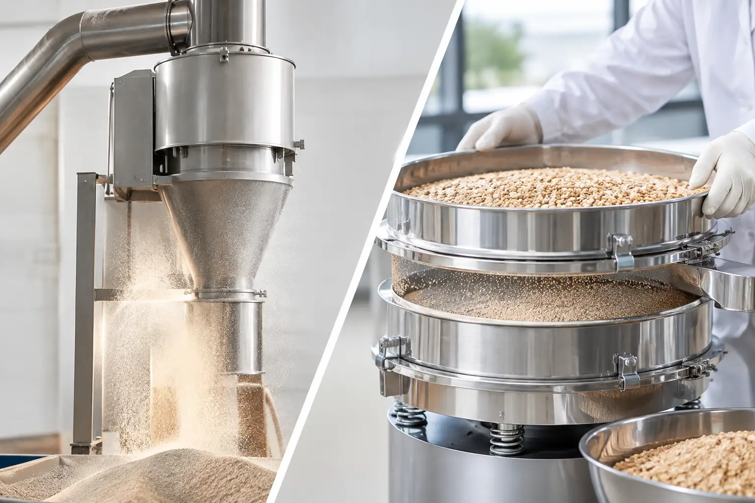
A rotary valve, commonly called a rotary airlock valve or rotary feeder, uses a pocketed rotor turning inside a housing. Material enters the pockets from above, travels with the rotor, and discharges below. The rotor creates a series of moving chambers that allow solids to pass while limiting air movement between the inlet and outlet.
This function makes rotary valves common below dust collectors, baghouses, cyclones, hoppers, bins, and receivers. In pneumatic conveying systems, they are frequently installed at a discharge point where the process must transfer material into a lower-pressure or higher-pressure zone without allowing excessive air leakage. In gravity applications, they can provide controlled, continuous discharge from a hopper or process vessel.
A rotary valve can also contribute to feed-rate control, but it should not automatically be treated as a precision feeder. Actual delivery rate depends on rotor volume, speed, pocket fill efficiency, material bulk density, and the consistency of material flow into the valve. Fine cohesive powders, fluctuating bulk density, bridging, or poor hopper design can make volumetric performance inconsistent. Where formulation accuracy is critical, a loss-in-weight feeder, weigh belt feeder, or other gravimetric system may be needed ahead of or in place of a simple rotary valve.
The Operating Variables That Matter
Air leakage is central to rotary valve performance. Clearance between rotor tips and the housing must be sufficient to prevent metal contact, yet small enough to limit leakage. Higher pressure differentials increase the significance of that clearance. Leakage can reduce pneumatic conveying efficiency, affect dust collection balance, and create material carryover or contamination concerns.
Material characteristics also determine rotor and housing design. Abrasive minerals may require hardened surfaces or wear-resistant construction. Sticky, hygroscopic, or heat-sensitive products may need special finishes, cleanout features, conditioned air, or alternative discharge technology. Friable products can break down if they are sheared between rotor tips and the housing. In sanitary food, pharmaceutical, and nutraceutical operations, cleanability, inspection access, and validated material contact surfaces may drive the selection as much as throughput.
Capacity is not simply a catalog value. A valve rated for a certain volumetric flow may deliver substantially less when the product does not fully fill the pockets, fluidizes at the inlet, compacts under head load, or becomes trapped in a low-clearance design. Selection should be based on tested or well-characterized material properties and the full operating envelope, not a maximum theoretical displacement.
What a Diverter Valve Does
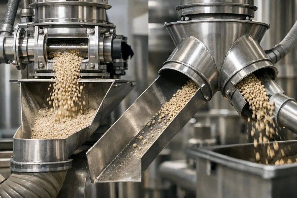
A diverter valve changes the route of bulk material. Instead of metering solids through rotating pockets, it moves an internal element – such as a plug, tube, flap, or slide – to direct material from one line or chute to another. Its purpose is distribution, line selection, or destination changeover.
A diverter valve may send powder from one pneumatic conveying line to two or more receiving bins, choose between a production hopper and a reclaim hopper, or direct material to packaging, blending, storage, or an off-spec destination. In a gravity system, it can split or switch the path beneath a bin or process vessel. The design must match whether the product is moving by gravity, vacuum conveying, pressure conveying, dilute phase, dense phase, or another transfer method.
Unlike a rotary valve, a diverter valve typically does not provide continuous metering or act as a primary airlock. It is normally positioned where the process needs to make a deliberate route selection. Some applications require the valve to shift only when flow has stopped. Others require a design capable of switching frequently or operating under conveying pressure while maintaining a reliable seal at the inactive branch.
Why Diverter Design Is Application-Specific
The wrong diverter geometry can become a restriction, leak point, or product hang-up zone. Elbows, abrupt transitions, dead pockets, and poor line alignment are especially problematic with cohesive powders, fragile agglomerates, abrasive materials, and products with strict sanitation requirements.
For pneumatic conveying, the diverter must maintain the line bore and internal geometry needed for the selected conveying regime. A pressure-capable design may need seals that withstand differential pressure without allowing leakage into an idle line. For gravity flow, the critical issue may be whether the valve provides a steep enough flow path and sufficiently open passage to prevent bridging or buildup.
Clean-in-place requirements, allergen changeover, batch traceability, and contamination control can further change the preferred design. A multi-port diverter that supports high routing flexibility may introduce more internal surfaces and seals to inspect. A simpler two-way valve may be easier to validate and maintain when routing options are limited.
Rotary Valve vs Diverter Valve: The Functional Difference
The clearest distinction is this: a rotary valve moves material through a discharge point in controlled increments; a diverter valve selects the path that material will follow. Many production systems require both.
Consider a powder receiver discharging into a pressure conveying line that feeds one of two blend systems. A rotary airlock below the receiver can discharge the powder while maintaining the pressure boundary. A diverter downstream can route the conveyed product to Blend Line A or Blend Line B. Replacing the rotary valve with a diverter would not provide controlled airlock discharge. Replacing the diverter with a rotary valve would not provide reliable destination selection.
The sequence and controls matter as much as the individual components. A diverter should confirm its selected position before material transfer begins. A rotary valve speed may need to coordinate with blower performance, downstream receiver level, feeder output, or a batch control recipe. Interlocks should prevent product from being sent to an unavailable vessel, an unsealed line, or a destination with insufficient capacity.
Selection Criteria for a Reliable System
The most effective specifications begin with the process requirement and work outward. Material data should include bulk density range, particle size distribution, flowability, moisture, temperature, abrasiveness, friability, and any tendency to segregate, smear, bridge, or fluidize. Those properties affect valve geometry, clearances, drive sizing, wear protection, and the need for flow-assist equipment.
Process conditions require the same discipline. Define required throughput at normal and peak rates; pressure or vacuum conditions; operating temperature; duty cycle; allowable leakage; cleaning method; and the consequences of cross-contamination. A valve that performs adequately during a short campaign may not hold up under continuous production with abrasive product or frequent routing changes.
System integration should receive equal attention. The inlet and outlet transitions must support consistent flow. Nearby filters, blowers, feeders, hoppers, and receivers must be sized around the valve’s real operating behavior. Controls should provide position feedback for diverters, rotation or speed feedback for rotary valves, and alarms for conditions such as stalled rotors, failed actuators, high torque, or a line selected out of sequence.
Maintenance access is a production requirement, not an afterthought. Rotary valves need planned inspection for rotor wear, seal condition, bearing performance, and pocket buildup. Diverter valves need accessible seals, actuator components, and internal surfaces that can be cleaned or inspected without excessive line disassembly. In highly abrasive service, replaceable wear liners and planned spare-parts strategy can materially reduce unplanned downtime.
Avoiding Common Specification Errors
One frequent error is selecting on nominal line size alone. A valve may physically fit a 6-inch line but still restrict flow, create an unfavorable transition, or lack the pressure rating needed for the conveying system. Another is assuming that a rotary valve will solve upstream flow problems. If material bridges in the hopper or ratholes above the inlet, the valve receives an inconsistent supply and cannot create stable feed by itself.
It is also risky to specify a diverter based only on the number of outlets. The valve must be evaluated for routing frequency, sealing requirement, material buildup risk, cleanability, actuator response, and control confirmation. For hazardous dusts or regulated production, the selection must also align with the facility’s safety analysis, containment requirements, and applicable validation standards.
Proc-X approaches these decisions as part of the complete material-handling system. The objective is not merely to install a valve, but to establish predictable material movement from source to destination under actual plant conditions.
The right component becomes clear when its role is defined before its model is chosen: use a rotary valve where controlled discharge and airlock performance are required, and use a diverter valve where the process must direct material with confidence. When both functions are needed, engineer them as coordinated parts of one process path.