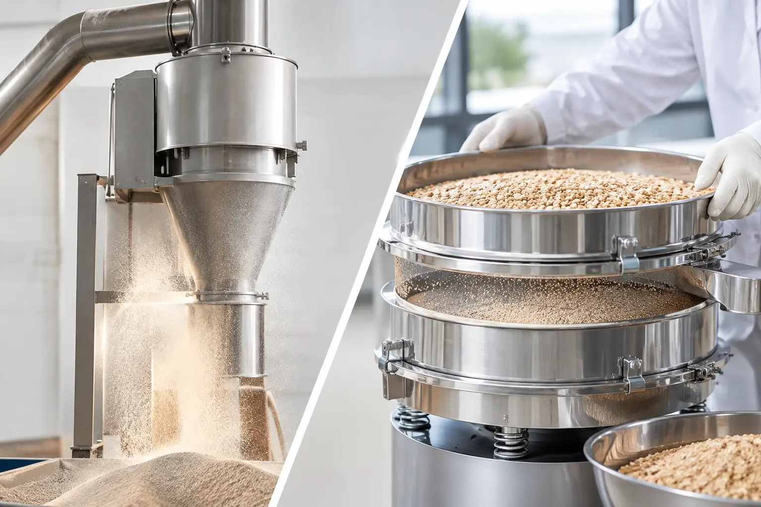
Abrasive material handling is rarely limited by the ability to move material from one point to another. The real constraint is how long the system can move it accurately before elbows, valves, feeders, diverters, classifiers, and conveying lines begin to lose their intended geometry. Once wear changes a flow path or introduces contamination, production rate, product quality, maintenance cost, and safety can all be affected.
For manufacturers processing silica, alumina, ceramic powders, minerals, metal powders, abrasives, catalysts, fertilizers, or other hard particulate materials, wear must be addressed as a process-design issue. A harder liner alone is not a complete answer. The system must account for the material, the transfer method, operating duty, equipment interfaces, and the consequences of component degradation over time.
Why Abrasive Materials Wear Systems Differently
Abrasiveness is not a single material property. It is the result of several interacting conditions: particle hardness, shape, size distribution, concentration, moisture, velocity, impact angle, and the material of construction. A fine, dry powder may erode a pneumatic line through sustained high-velocity sliding. A coarser granular product may damage an elbow or chute through repeated direct impact. A moist material can introduce a different problem by building up in low-velocity zones, then releasing unevenly and accelerating localized wear.
The same material can create very different wear patterns in different parts of a plant. A screw feeder may experience abrasion along flights and trough surfaces. A rotary valve may lose clearance control at the rotor and housing. In pneumatic conveying, bends, tees, receiver inlets, and directional changes often become the highest-risk locations. In mechanical conveying, transfer points, discharge chutes, and bearing protection require close attention.
Wear also has consequences beyond replacement-part expense. A worn rotary airlock can reduce pressure control and conveying efficiency. A damaged feed screw can change feed accuracy. A thinned pipe wall can fail unexpectedly. If equipment geometry shifts, particle velocity and impact behavior can shift with it, accelerating damage and making performance less predictable.
Start With Material and Duty-Cycle Data
Effective abrasive material handling begins with a clear material profile. Mohs hardness is useful, but it does not replace application testing or process knowledge. Particle morphology, bulk density, particle-size distribution, moisture content, flowability, friability, and temperature all influence how material behaves against equipment surfaces.
The duty cycle matters just as much. A line operating intermittently for two hours per day does not face the same design requirement as a continuous process running multiple shifts. Required production rate, annual tonnage, conveying distance, elevation changes, number of directional transitions, and acceptable shutdown windows should be established before selecting transfer equipment or wear materials.
This information helps engineers distinguish between a component that needs modest protection and a location that requires a purpose-built wear strategy. It also prevents an expensive mistake: specifying high-cost wear materials across an entire system when only a few concentrated impact zones are driving maintenance demand.
Test the Actual Product When Possible
Published material data is a starting point, not a final design basis. Source changes, recycled content, particle-size adjustments, drying conditions, and upstream milling can alter abrasive behavior. When the process is new or the operating conditions are demanding, testing the actual material under representative conditions provides a more reliable foundation for equipment selection.
Testing can also reveal competing priorities. A transport condition that minimizes pipe wear may increase particle degradation or energy use. A low-velocity design may reduce erosion but create settling risk for dense material. The correct approach depends on the product and the process objective, not on a generic conveying rule.
Design the Transfer Path to Reduce Impact
The most durable system is not necessarily the one with the hardest components. It is the one that controls where and how the material contacts equipment surfaces.
Every abrupt change in direction creates an opportunity for impact and erosion. Poorly designed chutes, sharp elbows, restrictive transitions, and improperly located diverters concentrate material energy in small areas. Over time, these locations become maintenance hotspots. Designing for gradual directional changes, controlled material trajectories, and consistent flow can substantially reduce localized damage.
In pneumatic systems, conveying velocity must be selected with care. Higher velocity can keep material suspended and maintain throughput, but it increases erosive energy at bends and fittings. Lower velocity can reduce wear but may increase the risk of saltation, plugging, or unstable conveying. Dense-phase conveying can be beneficial for some abrasive materials because it can operate at lower gas velocities, but it is not universally appropriate. Material permeability, line routing, batch requirements, and flow stability determine whether it is a sound fit.
For gravity-fed systems, the goal is often to prevent uncontrolled free fall and direct impact. Chute angles, liners, ledges, flow-control devices, and vessel inlet design should guide material into the next process step without creating dead zones or excessive velocity. A chute that appears simple on a layout drawing can become a chronic maintenance problem if the incoming stream strikes a narrow point at full speed.
Select Wear Protection by Failure Mechanism
Wear materials should be selected based on the expected failure mode, not by default. Hardened steel may perform well where moderate abrasion and impact occur together. Ceramic liners can provide excellent resistance to sliding abrasion, particularly in pipe bends and chutes, but may be less suitable where severe shock loading or installation constraints are present. Basalt, polyurethane, rubber, specialty alloys, and replaceable wear plates each have a place when matched to the application.
The installation method matters as well. A liner that is difficult to inspect or replace can extend an otherwise routine shutdown. In high-wear locations, replaceable modules or spool pieces may provide a better lifecycle outcome than a permanently lined component. Access doors, cleanout points, and inspection ports should be designed around real maintenance tasks, not added as an afterthought.
Wear protection also must not compromise product requirements. In pharmaceutical, food, battery, additive manufacturing, and high-purity chemical operations, material compatibility and contamination control may limit the available liner and construction options. The design must balance wear life with cleanability, containment, validation requirements, and product-contact standards.
Build Maintenance Into Abrasive Material Handling
Abrasive equipment does not fail without warning in every case, but the warning signs are often missed when inspections are informal. A structured maintenance plan should identify predictable wear points and define what operators and maintenance teams need to measure or observe.
Useful indicators include declining feed accuracy, unexpected pressure changes, rising blower demand, air leakage, material accumulation, changes in conveying time, vibration, and repeated localized repairs. Ultrasonic thickness measurement, inspection of replaceable bends, and documented wear mapping can help maintenance teams forecast component life instead of reacting after a failure.
Spare-parts planning should focus on critical-path components. Keeping every possible part in inventory is rarely economical. Maintaining access to high-risk elbows, valves, feeder components, liners, and seals can prevent a small wear issue from turning into an extended outage. The right inventory level depends on lead time, production schedule, replacement complexity, and the cost of lost capacity.
Treat Interfaces as Part of the System
Abrasive wear often concentrates at equipment boundaries. A feeder may be properly specified, but its discharge connection can create a restrictive transition. A pneumatic line may use wear-resistant elbows, while the receiver inlet remains unprotected. A mill discharge may accelerate product into a downstream valve that was selected only for flow capacity.
This is why abrasive material handling should be engineered as an integrated system. Feeders, transfer lines, air systems, dust collection, valves, receivers, controls, and downstream processing equipment must operate within compatible pressure, velocity, and capacity ranges. Controls should also provide the visibility needed to identify developing restrictions or abnormal operating conditions before the process becomes unstable.
For plant expansions, the challenge is often more complex. New equipment may increase production rate through existing transfer infrastructure that was not designed for the additional abrasive duty. A review of the full material path can identify whether higher throughput will create unacceptable velocity, pressure loss, or wear at legacy components.
Engineer for Predictable Lifecycle Performance
The objective is not to eliminate all wear. In abrasive service, wear is expected. The objective is to control it, localize it to serviceable components, and prevent it from affecting safety, quality, or production commitments.
That requires disciplined application engineering: characterize the material, define the operating duty, model the transfer path, protect known wear zones, and make inspection and replacement practical. For complex processes, one coordinated engineering standard across material handling, processing equipment, controls, and maintenance access reduces gaps between individual machines.
When abrasive materials are treated as a system-level design condition rather than a component-selection problem, manufacturers can plan maintenance with greater confidence and keep equipment performance aligned with the production schedule.